All posts by keannan09

Final Project – Motion Sensor

For the final project my partner Dwayne and I decided to make an Arduino based motion sensor. If was a challenge at first for us to find an interactive project for the final. Then we came across the motion sensor and we kind of just ran with the idea. We thought it would be fun and there were so many ways to make it into an interactive project.

Bill Of Materials

  • PIR sensor: The Passive Infrared Sensor measures infrared light from objects in its field of view.
  • Jumper wires
  • Arduino Uno
  • Breadboard
  • USB cable
  • Arduino Software

IMG_4142

Above is a image of the components (Bill of materials) we used for this project.

IMG_4143

First step we began connecting all the jumper wires from the breadboard to the Arduino. We connected a jumper wire (green jumper wire) from pin2 to row one on the breadboard which is the input for the PIR sensor. The second jumper wire connects from pin 5V and row 2 on the breadboard. And lastly the ground pin connects to row 3. These three jumper wires are the powers the PIR sensor from the Arduino (power supply).

IMG_4144 IMG_4145

Next we connected the PIR sensor to the breadboard. The ground pin on the PIR sensor connects to the ground row. The power pin connects to the 5V row and the output pin connected to the pin 2 on the Arduino.

IMG_4146

Next we connected the LED to the arduino. The purpose of the LED when lit the buzzer is supposed to go off and to show us that their is power running through the board.

IMG_4303IMG_4304

After we connected the piezo buzzer which is that black component showed above. This thing makes the most annoying noise ever but its purpose to go off when motion is detected by the PIR sensor.

THE CODE

FullSizeRender (2)

Final Project Idea – Mood Lamp

For this project my partner Dwayne and I chose to create an interactive mood lamp. At first we were just going to create a mood lamp that lit up a variety of colors until we found out that the project had to be interactive in some way. Knowing that we chose to make an interactive mood lamp that lights up when touched. It also changes color due to your mood.

touch

For this project we will be using a touch dome light which will light up when touched.

Color Mixing Lamp – Project 04

Creating a lamp using tricolor LEDs and photoresistors.

Bill Of Materials:

  • 13 Jumper wires
  • 6 resistors: 3, 220 OHM resistors & 3, 10 KilOHM resistors
  • 1 LED
  • 3 photoresistors
  • 1 Gel

THE CODE:

Screenshot 2014-11-02 17.35.33 Screenshot 2014-11-02 17.35.45

The coding is getting easier and easier with ever project that I do but im still having troube with it. As you can see I didnt really insert any comments because Im not too sure what the functions are actually doing. I understand the different coding functions but im not too sure of what does what in the circuit.

IMG_3421

The image above are the materails I used to get this project done.

IMG_3420IMG_3422

I started building this circuit by connecting the resistors to the breadboard. I first but in the three 220 OHM resistors. Next I connected the three 10 kilOHM resistors.

IMG_3424

The next step was to connect the three photoresistors that were included in this project.

IMG_3425IMG_3426IMG_3428

I then began connecting all the jumper wires to the breaboard. After I began connecting the jumper wires from the breadboard to the Arduino Uno.

IMG_3429

And lastly I connected tri color LED.

Part II- QUIZ

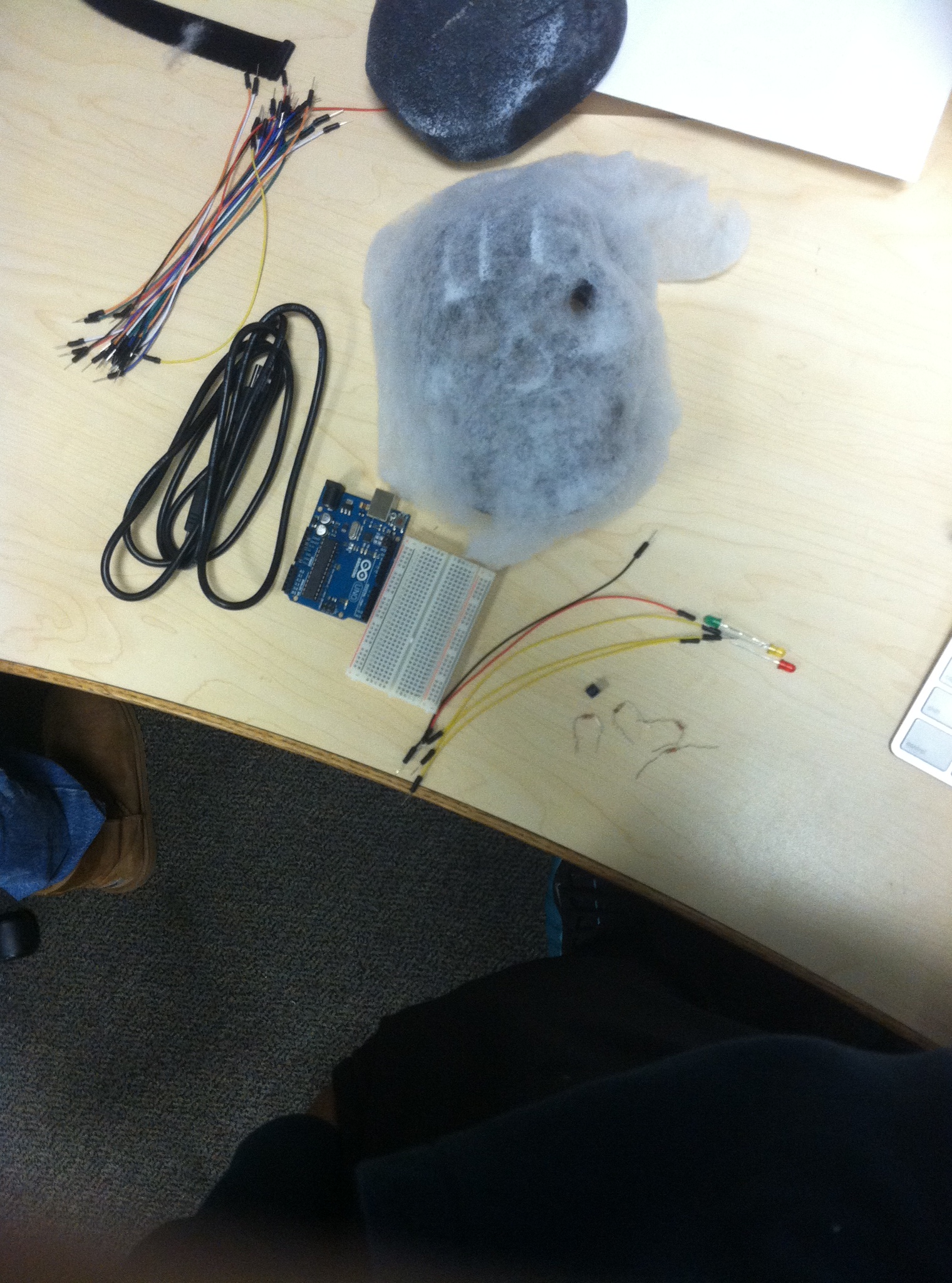
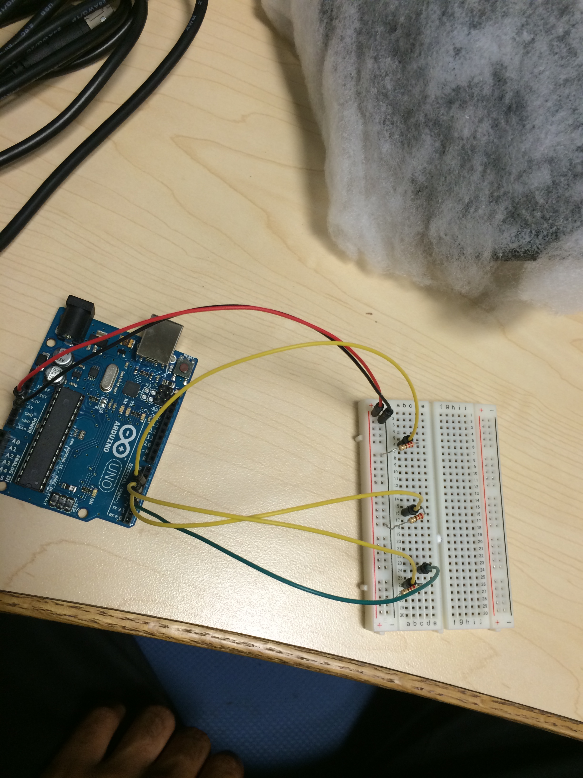
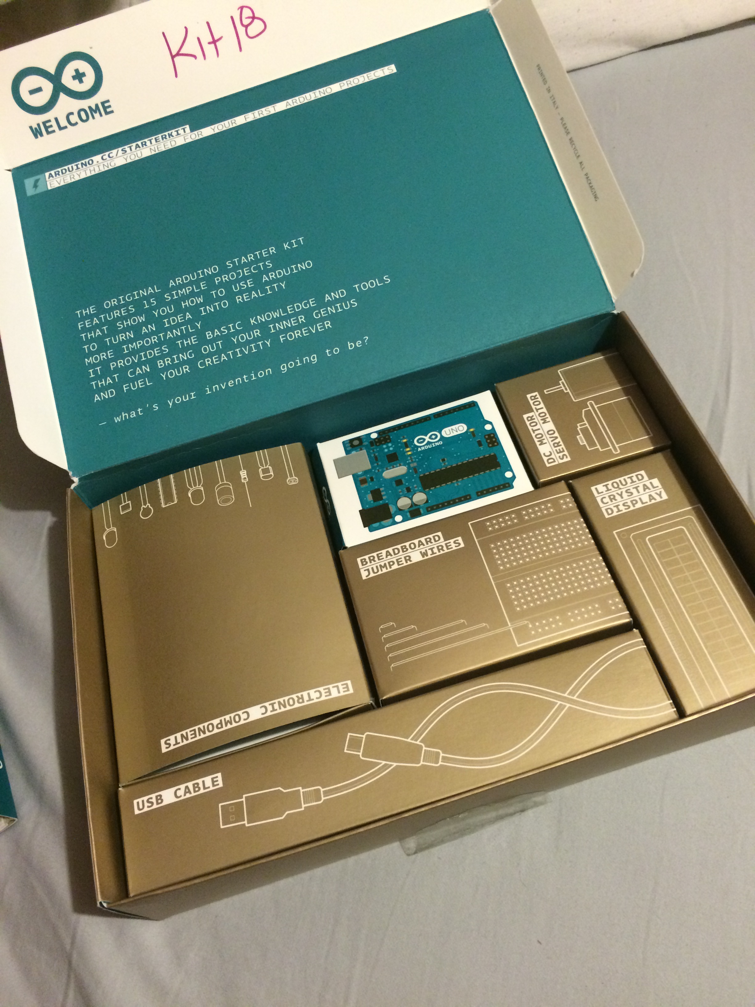
1.) What is Arduino?

Arduino is said to be the “brain” or “heart” of your circuit. Arduino is basically a simple computer that you program to do what you want.

2.) What is electricity? Current? Voltage? Resistance?

Electricity is a form of energy that powers most things around us. Current, in terms of electrical current is the flow of an electric charge. The electric charge running through a wire is current. Resistance basically controls the voltage running through the wire.

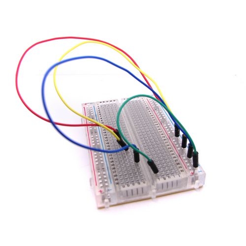
3.) What is a circuit? How does electricity flow in a circuit?

A circuit is a closed loop consisting of conductors and components where electricity can flow. Electricity flows from a higher voltage to a lower voltage.

4) What is Ohm’s law? When might you use it? How would you use it?

Greog Ohm was the person who created Ohm’s law. Ohm’s law combines the elements of voltage, current, and resistance and tells how they are related to each other.

5.) What is a series circuit? Parallel circuit?

A series circuit is a circuit in which the resistors are arranged in a way where current has only one path. A parallel circuit is basically the same idea as the series circuit but it includes 2 or more paths for current to flow through.

6.) What is the difference between digital and analog signal/voltage? Describe an example.

Analog circuits are harder to design than digital circuits. Digital components are used to make the design simpler. A high voltage represents one value and a low voltage represents the other. 

7.) What is code?

Code is basically the instructions. It’s what I like to call special text that you use in computer programming to basically program stuff to work and do specific things.

8.) What is a variable? How is it used in Arduino?

Variables in Arduino is a place to store a piece of data. When a variable is declared it can be used by putting the variable equal to the what you want to store with the assignment operator. “The assignment operator tells the program to put whatever is on the right side of the equal sign into the variable on the left side.”

9.) What is a function? How is it used in Arduino?

A function is exactly what it is, a function. Its basically something you create to do a specific task. Functions are used in arduino for many different reasons like. It helps keep code organized, lessens errors, makes it easier to reuse code in other programming etc.

10.) What two functions are required in Arduino code? What do they do?

Setup() and loop() are two required functions in Arduino code.

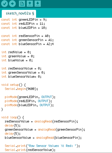
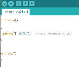
11.) Write one function that sets the pins on an Arduino.

Screenshot 2014-10-28 21.19.47

12.) How do you end a statement in Arduino?

You would use a break.

13.) What are curly braces/brackets used for in Arduino?

Curly brackets are used for functions, loops, and conditional statements.

14.) Describe one digital function and one analog function.

One example of a digital function would be “digitalWrite()”, which allows you to give a high or low to a digital pin. An example of an analog function is “analogWrite()”. This analog function can be used to light an LED to different levels of brightness and it can also drive a motor at different speeds.

15.) What are conditional statements in Arduino? Name one and describe its use.

Conditional statements lets a program carry out a piece of code based on a decision. An example of a conditional statement in arduino is an “if” statement basically used to carry out a block of commands.

16.) What is pulse width modulation (PWM)? How does it work? When might you use it in Arduino?

You can use a PMW to control the brightness of an LED.

17.) What is a multimeter? How do you use one?

You can use the multimeter to measure DC and AC voltage, DC current, resistance, continuity, and test diodes.

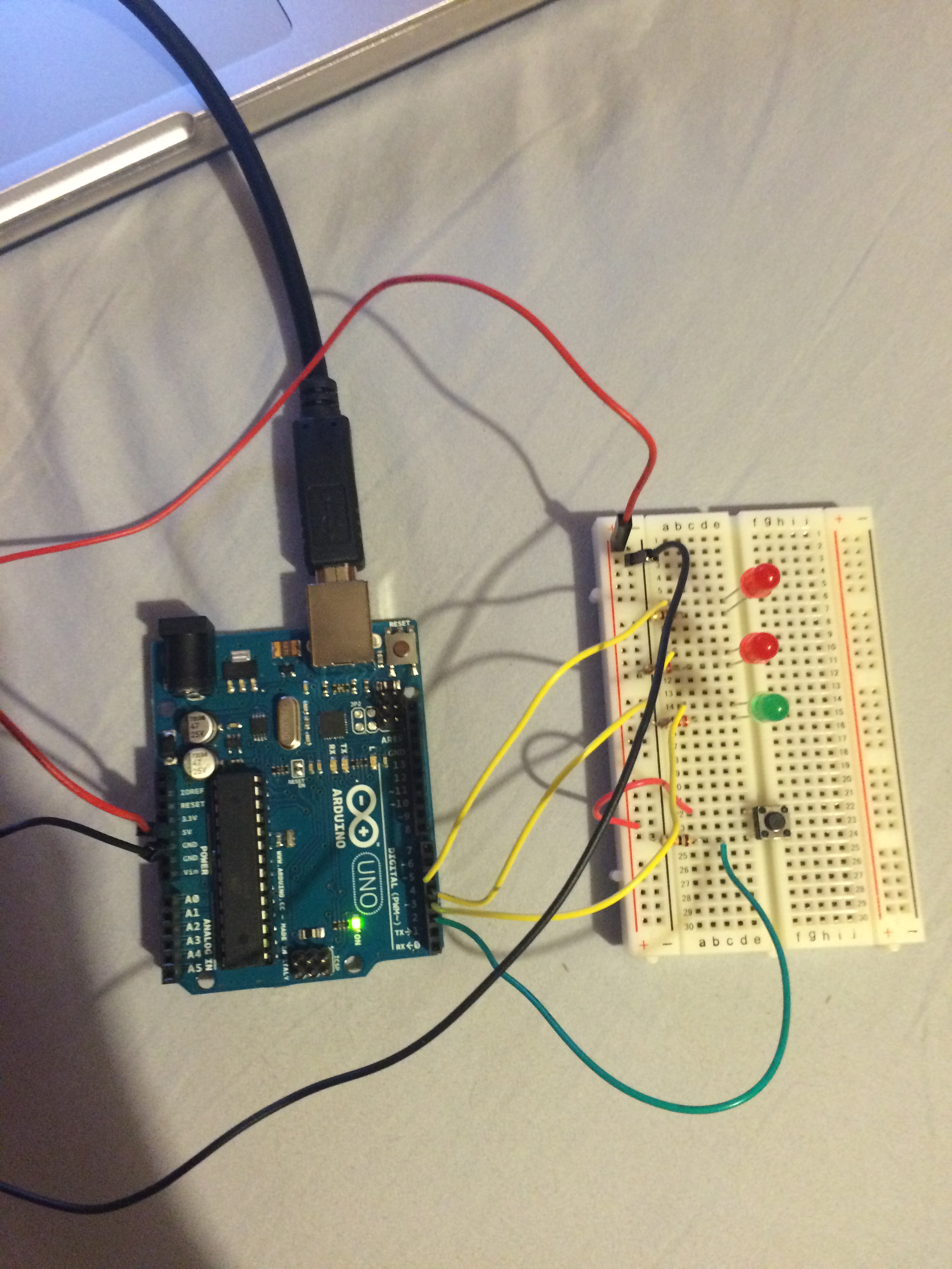
18.) How do you get code from your Arduino Sketch to an Arduino? What four things should you check for/do?

You can get code from your Arduino Skecth to an Arduino by plugging it up to you computer using the USB cable. First you should click tools and check to make sure that its on the right board. Next you would check to see if its on the right serial port. After you would click verify then upload and if the coding is good and the components are wiried up correctly matching your code your circuit should work.

19.) What is the serial monitor for? How do you invoke it in your code? On the Arduino IDE?

The serial monitor is basically used for communication from the Arduino to the computer. You can use digital pins 0 (RX) and 1 (TX) or by using the USB cable.

20.) What is baud rate?

The baud rate is the rate at which information is transferred in a communication channel

Resources:

Part I – Sensor/Actuator Walk

  • Arduino Uno

Basically the “brain” of all projects found in the Arduino Projects book.

IMG_3326

  • Battery snap

Used to connect a battery to power a device. By putting the batteries into this remote which already contains a battery snap is what allows it to work.

IMG_3310

  • Breadboard

A platform used to connect components when building a circuit.

IMG_3328

  • Capacitors

Capacitors store energy in a circuit. Found in many electronics  and works like a temporary battery. There capacitors in laptops.

ef

  • DC motor

DC motors convert electrical energy making objects move. For example a toy car built with a DC motor allows the car to move in various directions.

IMG_3329IMG_3317

  • Diode

A diode is used to make sure that electricity only flows in one direction.

dtgr

  • Gels

The main purpose for Gel which come in many different colors is to filter out different wavelengths of light. For example gels are used a lot in film production. When lighting you can turn a very bright white light into a red one by putting a red gel over the light.

hacking4hacking5

  • H-bridge

This component controls the polarity of the voltage in a motor.

  • Jumper wires

Used to connect components to each other to transfer electrical signals. These are some jumper wires connected to a breadboard.

IMG_3318

  • Light Emitting Diodes (LEDs)

This is a diode that lights up when electricity  passes through it. For example the LEDs in this skull head lights up when you turn it on.

hacking

  • Liquid Crystal DIsplay (LCD)

An LCD is graphic display. They many different styles of LCDs but its in a many things we use on a daily basis for example your phone has a LCD in it. When the LCD gets messed up it affects the display.

IMG_3315

  • Male header pins

Helps to make connecting things easier.

hacking3

  • Optocoupler

Allows you to connect two circuits that might do completely different things to the same power supply.

  • Piezo

This component works due to vibration. When it senses vibration it creates a noise.

  • Photoresistor

Is a resistor that changes due to the amount of light that hits it.

  • Potentiometer

This is a type of resistor that controls voltage when the knob is turned. An example of this would be my living room light. When the knob is turned from the left side to the right the bulb brightens.

IMG_3311hacnking7

  • Pushbuttons

Pushbuttons are switches that closes the circuit when pushed. One example of this would be the power button on the Mac. When you push the button the screen comes on.

IMG_3330IMG_3331

  • Resistors

Resistor basically resist the flow of energy in a circuit. Most times used in circuits so that a short wouldn’t occur due to too much voltage. Different resistors have different values and use for how much voltage you would like to resist.

  • Servo motor

A servo motor is a type of motor that can only rotate 180 degrees. Basically tells which direction the object moves according to the impulses programmed. For example a toy helicopter would have a servo motor and which ever direction you choose on the controller the helicopter is programmed to move in that direction.

  • Temperature Sensor

A temperature sensor’s voltage varies depending on the component’s temperature. For example the air conditioning on a city bus automatically comes on when its a certain temperature outside vice versa with the heating system.

  • Tilt sensor

This sensor work when tilted pretty self explanatory. So tilting the object make the circuit work. For example some cars have a tilt sensor alarm which goes off if your car is tilted.

  • Transistor

Can operate as an electronic switch.

  • USB Cable

A Universal Serial Bus (USB) is used for connection, communication and power supply from your computer to your device. For example the USB in Arduino is used to basically transfer code from the Arduino Sketch to the Arduino board allowing the Arduino to perform as you programmed it to. Another example would be using a USB to sync files from your phone onto your computer or to power your device.

IMG_3316

Midterm Project

At first we were really undecided with what we really wanted to do. We searched online for some arduino projects and didn’t find anything we really wanted to do. So we decided to use one of the projects in the arduino projects book. We picked project 02 Spaceship Interface and we were going to remix it so that we could use the led’s as eyes for the skull head. We ended up going online for more arduino project ideas and found the Traffic Light project. After we decided that we would combine both the Traffic Light and the Spaceship Interface projects.

Bill of Materials

  • Arduino Kit
  • Arduino Software
  • Arduino Uno board
  • Breadboard
  • USB cable
  • Jumper wires: 3 yellow, 2 red, 1 black
  • 3 led’s: 1 green, 1 yellow, 1 red
  • 4 resistors
  • 1 switch

IMG_7637.JPG

Above are the Bill of Materials that we used for this project.

Screen Shot 2014-10-23 at 12.49.01 PMScreen Shot 2014-10-23 at 12.48.27 PM

The images above is a screenshot of the coding…

IMG_3121IMG_3122

The first thing we chose to do was to connect the jumper wires from the arduino board to the breadboard. The 3 yellow jumper wires were put into pins 3, 4, and 5 on the arduino board from there we connected it to a5, a15, and a25 on the breadboard. Next we put the red jumper into 5V on the arduino board then connected to the plus side one the breadboard. The black jumper wire connects to GND on the arduino board and the other end is connected to the negative side of the breadboard. After we connected the green jumper wire to pin 2 on the arduino board and then to c24 on the breadboard.

IMG_3125

Next we connected the red jumper wire to the plus side of the breadboard then to a22. After we connected all of the LEDS. The green LED was connected pins e5 and e6 on the breadboard. The yellow LED connects to pins c15 and c16 on the breadboard. And the red LED connects to pins e25 and e26 on the breadboard. After we connected all the resistors and then the switch.

IMG_3126

We plugged in the USB to the cpu and then into the arduino board. Then we uploaded the code and it worked.

Heres a video.

Spaceship Interface.

For this assignment we were giving “The Arduino Starter Kit.” For this assignment we were asked to complete the Spaceship Interface project in the arduino projects book.

IMG_2966

The first step was to get familiar with the materials.

Bill of Materials:

  • Arduino Starter Kit
  • Mac notebook
  • Arduino 1.0.6 software
  • Arduino UNO board
  • Breadboard
  • Jumper Wires: 1 Red, 1 black, 3 yellow, 1 green, 1 orange
  • Led’s: 2 red, 1 green
  • 4 resistors: 3 gold, brown, orange red & 1 gold, yellow, black, brown
  • Switch
  • USB cable

IMG_2965

The next thing was to start connecting the different parts from the breadboard.

FullSizeRender

In the picture above the first thing I did was connect the resistors to the breadboard. I know it didnt matter really which row it was in just as long as it was all lined up correctly. But i played it safe and just decided to put everything together exactly how i seen it in the book.

IMG_2956

Next I connected the Led’s to the breadboard just like I seen it in the book. 2 red led’s and then the green follows.

IMG_2959

I then connected the switch everything was all great and dandy still.

IMG_2960IMG_2961-2

Next I started to connect the components that needed to be connected from the arduino board to the breadboard. I started with the red and black jumper wires and moved on to the yellow jumper wires. Im still connecting everything exactly how I see it in the book just to be safe. And everything still seems to be great and dandy.

Next I decided to work with the coding which I honestly didnt type out myself. I used an example on the arduino application. I’ve never coded in my life, I know nothing about coding and its really difficult for me so for this project I played it safe. When I pressed

IMG_2963

After I connected the small orange jumper wire and the green jumper wire.

Screenshot 2014-10-16 12.20.41

Next I decided to work with the coding which I honestly didn’t type out myself. I used an example on the arduino application. I’ve never coded in my life, I know nothing about coding and its really difficult for me so for this project I played it safe. When I pressed upload it said there was an error. Me not knowing anything about coding I couldnt tell you what was wrong with the coding. I followed the instructions from the arduino projects book step by step when I was connecting the components to the breadboard and from the breadboard to the arduino board. My project didnt work when I plugged in the USB from the computer to the arduino board. I believe the problem was the coding.

Super-Feature

I thought long and hard about this assignment because I had multiple ideas. I’m always creating interesting thoughts in my head that I wish I could bring to life. Most of these ideas are realistic while some of them aren’t. For this assignment I had to do a little research to find out if my ideas were already invented. While doing research I realized that two of my ideas are actually already invented. For example, what if clothes could clean itself? That would be really easy and less time comsuming right? Well apparently this idea is already in progress.

clothesline

Chemist said that future clothing made with modified cotton would be able to clean itself using sunlight. All you would really have to do is hang your clothes up in the sun, pretty simple and cool right? When I thought about this idea modified cotton never came to mind which is actually a great idea. My idea was to make some kind of spray that you could spray on your clothes to automatically clean it. They have dry shampoo for hair, I thought it’ll be a great idea to make an aerosol cleansing spray for clothes.

RESOURCES:

http://www.popsci.com/technology/article/2011-12/when-exposed-sunlight-chemical-coating-removes-filth-cotton-clothes

Drawdio

For this assignment we had to partner up with a classmate and document step by step us building a Drawdio. A Drawdio is basically a pencil that when you draw or write with it makes a sound.

Screen Shot 2014-09-18 at 1.51.03 PMScreen Shot 2014-09-18 at 1.51.16 PM

The first thing I did was put the resistors in the PCB which is the blue base and made sure they were in the right spot. For this project there were 4 different resistors. It was important that each resistor was in the right place. In the second image you can see that I didnt solder anything as of yet. The reason I didnt was to make sure that everything was in the right place.

Screen Shot 2014-09-18 at 1.51.25 PM

After I put the resistors in I then put the two ceramic capacitors. Which would be the little blue and yellow thing. Then I added the timer chip which would box right next to the two capacitors. After adding the timer chip I added the PNP transistor which are the other two black parts to the right in that order.

Screen Shot 2014-09-18 at 1.51.36 PM

After I got all the little parts in the right parts of the PCB I then began soldering them. The image above is the finished result of me soldering it.

Screen Shot 2014-09-18 at 1.51.46 PM

Next I connected the speaker. Connecting the speaker was another process. I had to solder two pieces of wire to the speakers before I could connect it to the PCB. I cut two peices of 3″ wire and then I removed 1/4th of the insultion from both ends of the wire. I soldered the exposed wire to the speaker then I connected the other side of the exposed wire to the PCB  and soldered it as well.  After I soldered in the battery holder in.

Screen Shot 2014-09-18 at 1.52.05 PM

I then sharpened the pencil and connected it to the PCB using a zip tie. After that I wrapped the copper wire around the base of the PCB and the base of the pencil and then around the front of the PCB. I then stuck the thumb tack in the base of the pencil. I put the battery in the battery holder and tried writing with the drawdio and unfortunately no sounds came out.

TROUBLESHOOTING?

I had difficulty with a few things during this project the main on was getting the drawdio to actually work which didnt work well in my favor. I had trouble figuring out where exactly the cooper wire needed to be. At first i thought it just wrapped aroung the pencil until i learned that it should also be touchign the front of PCB. I also wasnt sure if the thumb tack should go in the base of the pencil first of through the copper wire and then into the base of the pencil. I believe that it didnt work because I may have burnt the PCB with the soldering iron a few times. I also had trouble sharpening my pencil because the sharpener in the classroom is broken, just kidding.

UPDATES:

Bill Of Parts

  • PCB: This is a printed circuit board which eletrically connects electronic components.
  • IC1: Also known as the timer chip which is an integrated circuit chip basically used as a timer.
  • Q1: Also known as the PNP transitor is used to source a current.
  • C1: Which is a ceramic capacitor good for filtering high currency.
  • C3: Another kind of ceramic capacitor also good for filtering high currency.
  • C2: A 6.3V capacitor, inexpesive and good for general hacking. (polarized)
  • R1: This is a type of resistor that comes with brown, black, blue and gold or red, black, blue and gold markings on them in that order. Resistors reduce current flow.
  • R2: Also a resistor that comes with a brown, black, black, gold rings on it in that order. Also known as the default resistor and is most common.
  • RA: Another very common resistor which has brown, black, orange, and gold bands on it in that order.
  • RB: Comes with orange, black, yellow, and gold markings on it in that order. (Resistors do not contain polarity)
  • BATT: Also known as an AAA battery holder.
  • SPK: Also known as a small 8ohm speaker.
  • Copper foil tape: A conductive adhesive.
  • Thumbtack: A thumbtack is a thumbtack.
  • Pencil: same goes for a pencil.
  • Zip-tie: same goes for a zip tie.
  • Wire: and the same goes for a wire.

After the lighten talk in class I’ve realized that there is many other reasons why my Drawdio didnt work. For example soldering can be very tricky and I wasnt really too sure what was too much solder and what was too little solder. At a point during my soldering process I had connect two different leads together by accident which I was told can create a shortage in the circuit. It was really difficult to remove the access solder at this point. I tired using the se-soldering pump and I eventually was able to remove the access solder. During this I may have burned the PCB because it was so hard to melt the solder and be able to quickly remove it with the pump because the solder cools down really quickly. I also didnt consider polarity in this assignment. I didnt know that certain objects had polarity and that it mattered. This was also a big factor to why my Drawdio didnt work.

Teardown Process

For this assignment I decided to use a Nintendo Wii remote.

Screenshot 2014-09-16 21.07.20 Screenshot 2014-09-16 21.07.39 Screenshot 2014-09-16 21.07.51

Front, back and side view of the wii remote.

Screenshot 2014-09-16 21.08.05Screenshot 2014-09-16 21.08.29

The first step was to remove the battery back. The Wii remote I used for this assignment had a rechargeable battery thats why there are no batteries in the image above. After removing the battery back I took out the visible screws that as under the battery. Once I removed all the screws I was able to remove the top part of the Wii remote. Then I popped all the buttons out.

Screenshot 2014-09-16 21.09.30

The image above is the final result. I had to clip a few wires to get some of the pieces apart.